
27Q095 vs 27Q100: Hi-B Grade Choice for PV and Reactor Cores
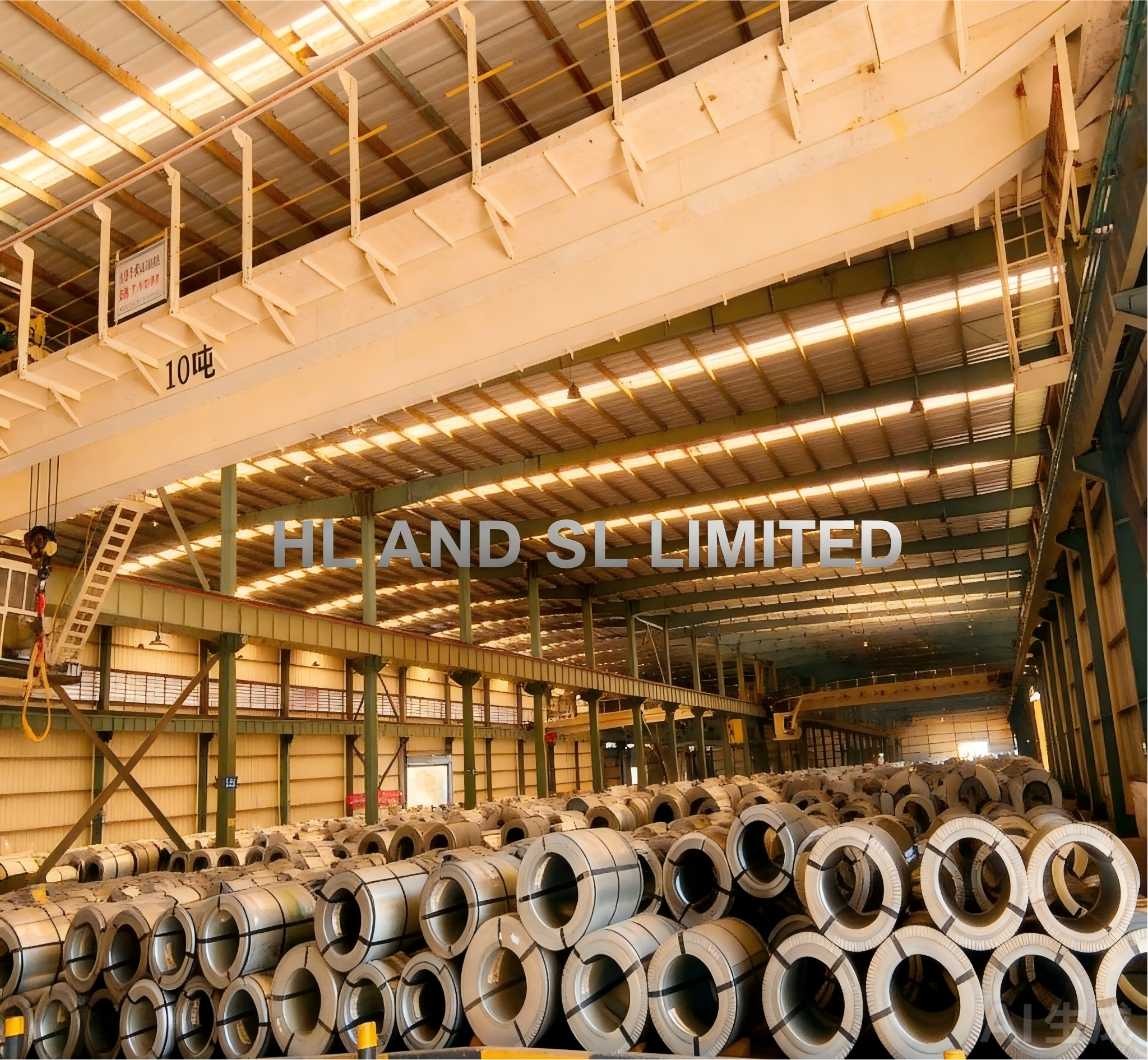
27Q095 and 27Q100 are both 0.27 mm Hi-B grain-oriented silicon steel. The line that separates them is the guaranteed maximum core loss at 1.7 T and 50 Hz: ≤0.95 W/kg for 27Q095 and ≤1.00 W/kg for 27Q100. Take 27Q095 when the core-loss budget is tight and the magnetic circuit is a high-efficiency power transformer or a photovoltaic (PV) DC converter transformer. Take 27Q100 when the circuit is a reactor or a general electrical equipment core and a 1.00 W/kg ceiling still clears the loss, temperature and noise limits of the design.
That is the short answer. The rest of this guide explains what the two grades share, how the 0.05 W/kg gap converts into watts inside an actual core, why the two application families pull in different directions, and which specification steps decide whether the chosen grade delivers the number printed on its datasheet.
The Shared Platform: What Both Grades Actually Are
Both grades sit in the same product family before any comparison begins. They are fully processed, final-annealed, Goss-textured grain-oriented electrical steel at 0.27 mm nominal thickness, delivered in coils or sheets for the construction of magnetic circuits. That description matches the scope of IEC 60404-8-7:2020, which covers cold-rolled grain-oriented electrical steel strip and sheet supplied in the fully processed state and intended for magnetic circuits.
The thickness also lands inside that standard’s grade series rather than the thin-gauge series. IEC 60404-8-7:2020 lists nominal thicknesses of 0.20 mm, 0.23 mm, 0.27 mm, 0.30 mm and 0.35 mm. IEC 60404-8-8:2017, by contrast, addresses thin non-oriented material at 0.05–0.35 mm and thin grain-oriented material at 0.05–0.18 mm. A 0.27 mm grain-oriented grade therefore belongs to the 8-7 framework, and citing the correct standard in a purchase order removes a common source of specification ambiguity.
Both grades also carry the B8 ≥1.88 T family specification where applicable. B8 is the flux density reached under an 800 A/m magnetizing field, so it is a statement about how much flux the material supports at a given excitation. In design terms it sets the ceiling on usable working flux density and the margin available before saturation effects become dominant.
Hi-B itself means high-permeability grain-oriented steel, in which strong Goss texture is developed along the rolling direction so that magnetic properties are best along that axis. This is why grain-oriented grades are specified for transformer and reactor cores rather than for rotating-machine stators and rotors, where non-oriented material is the normal choice.
What follows from all this common ground? At 0.27 mm, the two grades are not separated by orientation quality, delivery condition or thickness. They are separated by one loss tier. The selection question is therefore not which material is technically superior in general, but which loss ceiling matches a specific core-loss budget and magnetic circuit.
Reading the Grade Code Before You Compare Numbers
The designation itself tells a buyer where the difference sits. In this grade-naming convention, 27 denotes a nominal thickness of 0.27 mm, Q denotes grain-oriented material, and the three-digit suffix corresponds to the P1.7/50 ceiling multiplied by 100. So 095 means 0.95 W/kg and 100 means 1.00 W/kg. A specifier who can read the code knows the comparison before opening either datasheet.
P1.7/50 is the specific total loss per unit mass measured at a peak flux density of 1.7 T and a frequency of 50 Hz under sinusoidal magnetization. Because the test condition is fixed, the two grade ceilings are directly comparable to each other. That is precisely why the figure is used as a purchasing number rather than a general performance description.
What the 0.05 W/kg Gap Means for a Core-Loss Budget
The absolute gap is 0.05 W/kg. Expressed against the 27Q100 ceiling, 27Q095 is about 5% lower; expressed against its own ceiling, 27Q100 is about 5.3% higher. Both readings describe the same step, and neither is large in isolation. What matters is how that step scales with the mass of the core that will carry it.
ΔP0 = (1.00 − 0.95) × m = 0.05 × m (W)
where m is the effective core mass in kilograms.
Arithmetic illustration, not a measured result: for a core of 2,000 kg effective mass, the difference between the two ceilings corresponds to 0.05 × 2,000 = 100 W of no-load loss. This is a calculation using the two grade limits only. Any real core will differ according to working flux density, frequency content, processing quality and stacking method.
The practical use of that formula is a screening test, not a final answer. First calculate the no-load loss allowance your design can carry, including the margin your thermal and efficiency targets require. Then compare that allowance with the material ceiling. If the allowance falls between 0.95 and 1.00 W/kg — a narrow band — only 27Q095 covers it at the material level. If the allowance sits clearly above 1.00 W/kg, 27Q100 already satisfies the loss requirement and the remaining decision shifts to other criteria.
Two conditions reduce the weight of this comparison. First, if the design working flux density is well below 1.7 T, both grades will run below their ceilings and the absolute difference shrinks with the flux level. The ceiling comparison is most meaningful close to the 1.7 T test point. Second, in equipment where winding loss or load loss dominates total loss, a 5% step in no-load loss is diluted in the overall efficiency calculation. Evaluate total loss, not iron loss alone.
Why PV DC Converter Transformers Lean Toward 27Q095
The assigned application fit places 27Q095 in high-efficiency power transformers and PV DC converter transformers. The reasoning is structural rather than promotional. A PV converter transformer typically runs with a high duty cycle, so no-load loss is present for long periods rather than only during peak output. Enclosures and outdoor cabinets often leave limited thermal headroom, so every watt of core loss has to be removed by the cooling design. And in a generation asset, losses accumulate across the operating life of the plant.
Under those conditions the lower ceiling buys design freedom. A designer can hold the same working flux density and winding configuration and reduce no-load loss, or hold the same loss allowance and accept a slightly higher design flux. Both moves are trades inside the design envelope, not automatic efficiency claims. Whether the trade is worth taking depends on how close the original design sat to its thermal and efficiency limits.
The condition that weakens the case is worth stating plainly. If the working flux is constrained below 1.7 T by harmonic content, temperature rise or noise limits, or if the core mass is small, the absolute benefit of the 0.05 W/kg step is limited. Choosing 27Q095 by default, without running the loss budget, is not a decision — it is an assumption.
Documentation is a separate track from material choice. PV projects commonly require a declared material standard and a core-loss test report stating the measurement condition at 1.7 T and 50 Hz. Specifying IEC 60404-8-7:2020 as the reference standard and requiring the test condition in writing prevents later disputes about what the number on the certificate actually represents.
Where 27Q100 Fits: Reactors and Equipment Cores
The assigned fit for 27Q100 is power transformers, reactors and electrical equipment cores. Reactors deserve the closest look, because their magnetic circuit behaves differently from a transformer core. Reactor designs frequently include an air gap, and the flux waveform often carries harmonic components; some topologies also see a DC bias component. Core loss in a reactor is therefore coupled to temperature rise and audible noise in a way that a clean 50 Hz transformer core is not.
In that context, a single P1.7/50 figure cannot settle the selection. What 27Q100 offers is a defined 1.00 W/kg ceiling. When the reactor’s loss and temperature budgets are satisfied at that ceiling, the grade is a matched option, and there is no engineering reason to reserve margin that the design does not need. The choice should follow the budget, not a preference for the lowest available loss figure.
Noise is the second reactor-specific criterion. IEC 60404-17:2021 applies to the measurement of magnetostriction characteristics of grain-oriented electrical steel strip and sheet under an applied AC magnetic field at 50 Hz or 60 Hz. Where audible noise is an acceptance criterion for a reactor, a buyer can require a magnetostriction test report aligned with that method alongside the standard core-loss report.
27Q095 vs 27Q100 at a Glance
The table below compares only the attributes established for these two grades. It does not assume equivalence with any other supplier’s grade carrying a similar designation.
| Comparison dimension | 27Q095 | 27Q100 |
|---|---|---|
| Nominal thickness | 0.27 mm | 0.27 mm |
| Grade family | Hi-B grain-oriented, Goss texture, fully processed | Hi-B grain-oriented, Goss texture, fully processed |
| Max core loss, P1.7/50 | ≤0.95 W/kg | ≤1.00 W/kg |
| B8 | ≥1.88 T family specification, where applicable | ≥1.88 T family specification, where applicable |
| Stated application fit | High-efficiency power transformers; PV DC converter transformers | Power transformers; reactors; electrical equipment cores |
| Standard framework for 0.27 mm GOES | IEC 60404-8-7:2020 grade series (0.20–0.35 mm) | IEC 60404-8-7:2020 grade series (0.20–0.35 mm) |
| Selection trigger | The loss allowance falls in the 0.95–1.00 W/kg band or the efficiency target requires the lower ceiling | The 1.00 W/kg ceiling clears the loss, temperature and noise budgets with margin to spare |
Decision Checklist: Seven Steps From Spec to Purchase Order
Working through the steps in order keeps the grade decision attached to the design rather than to habit. Each step can be closed with a document, which is what makes the decision auditable later.
- Fix the magnetic circuit type. Record whether the core is a power transformer, a PV DC converter transformer, a series or filter reactor, or a general equipment core. The circuit type determines which criteria carry weight and which are secondary.
- Convert the loss budget into a W/kg ceiling. Calculate the no-load loss allowance, divide by the effective core mass, and apply the margin your thermal design requires. Compare the result directly with 0.95 and 1.00 W/kg. If the result sits between the two, 27Q095 is the only grade that covers it at the material level.
- Check B8 margin against the design flux. Confirm the working flux density leaves margin under the ≥1.88 T family figure, and account for any over-excitation or inrush condition the design must survive.
- Screen the harmonic and frequency content. If significant high-frequency harmonics are present, evaluate thinner gauges and filtering before committing to a 0.27 mm grade. Record the harmonic spectrum in the technical agreement so the operating range is explicit.
- Confirm coating and temperature class. Insulation coatings are not interchangeable across temperature ranges: organic coatings are commonly rated to about 180 °C, while inorganic coatings can extend to around 800 °C. Match the coating to the actual operating temperature and to the annealing cycle the core will see.
- Agree processing and annealing controls. Specify sharp tooling and controlled blanking clearance, and require stress-relief annealing at 700–800 °C where the process calls for it. Set a minimum bending radius of at least 10–20 times the sheet thickness, and require uniform stacking pressure without hammering or single-point lifting.
- Define storage, documentation and acceptance. Set warehouse humidity at no more than 60% with ventilation and no contact with acidic or alkaline substances; require assembly or anti-rust oil application immediately after processing. In the acceptance clause, name the applicable standard, the P1.7/50 test condition, the B8 requirement, the coating type, and any magnetostriction report needed for noise-critical equipment.
Use Cases in Brief
High-efficiency power transformers. Both grades are viable. The loss budget decides: 27Q095 where the allowance is tight, 27Q100 where a 1.00 W/kg ceiling already satisfies the efficiency and thermal targets.
PV DC converter transformers. The stated fit favors 27Q095, because continuous high-duty operation and constrained thermal headroom make the lower no-load loss ceiling worth the design margin it consumes.
Series and filter reactors. The stated fit favors 27Q100, subject to a harmonic screen. If the spectrum is dominated by high-frequency components, thinner gauges and filtering measures should be evaluated before the grade is fixed.
General electrical equipment cores. Also within the stated fit for 27Q100, where the 1.00 W/kg ceiling meets the loss budget and no additional margin is required.
Handling Conditions That Decide Whether the Grade Delivers
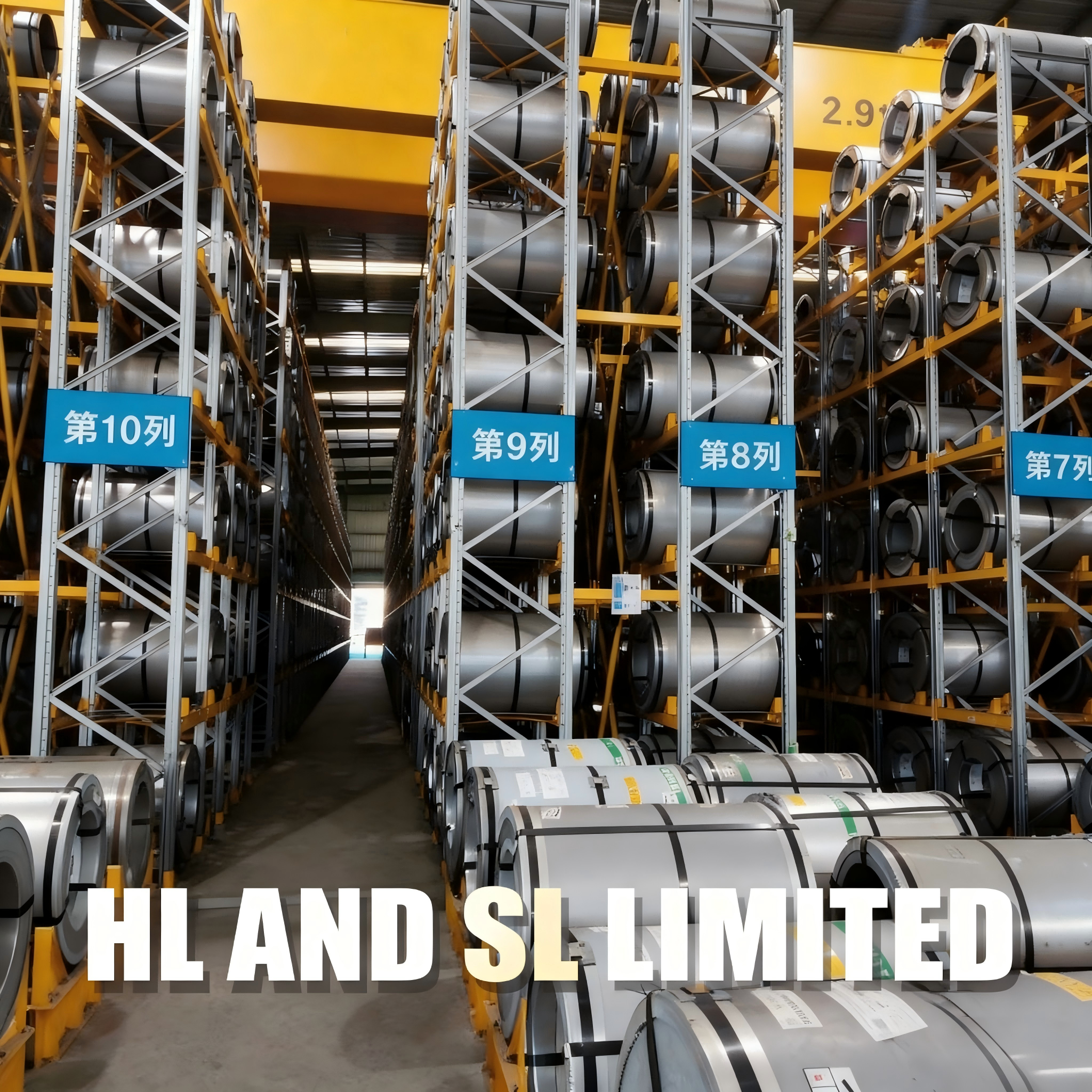
A material ceiling only sets the upper bound; the delivered core loss is decided in the shop. Shearing and punching introduce mechanical stress, so sharp dies and controlled blanking clearance matter, and stress-relief annealing at 700–800 °C is applied where the process requires it. Press-fitting should use torque control so pressure stays uniform and below the material’s yield strength.
Bending and transport damage are avoidable losses. The minimum bending radius should be at least 10–20 times the sheet thickness, sheets should stay flat in storage and transport, and single-point lifting or hammering should be prohibited. For stacking, uniform pressure is required rather than localized force.
Moisture and corrosion control protect both the coating and the magnetic surface. Storage humidity should not exceed 60%, with good ventilation and dryness; contact with acidic or alkaline substances must be avoided; and processed parts should be assembled or coated with anti-rust oil as soon as processing is complete.
Frequently Asked Questions
Do 27Q095 and 27Q100 fall under the same standard?
Both are 0.27 mm fully processed grain-oriented grades, and 0.27 mm is one of the nominal thicknesses covered by IEC 60404-8-7:2020, alongside 0.20, 0.23, 0.30 and 0.35 mm. ASTM A876-17e1 is a separate specification for flat-rolled, grain-oriented, fully processed low-carbon silicon-iron electrical steel, and IEC and ASTM requirements should not be assumed equivalent grade by grade without a documented comparison. Name the applicable standard and grade explicitly in the purchase order.
Does the 0.05 W/kg difference matter for a reactor core?
It depends on how the reactor actually operates. Where the core is large, runs continuously and has limited thermal headroom, the difference scales as 0.05 W/kg multiplied by the effective core mass and produces a measurable no-load loss gap. Where harmonic content dominates the loss or winding loss carries most of the total, the grade-to-grade step is diluted, and a thinner gauge or a filtering measure should be evaluated first. The comparison is meaningful only at a stated working flux and waveform.
How do I convert the P1.7/50 figure into a purchase specification?
Write three things into the specification: the test condition (1.7 T, 50 Hz), the ceiling (≤0.95 W/kg for 27Q095 or ≤1.00 W/kg for 27Q100), and the acceptance method, including sampling and the test report required at incoming inspection. Add thickness tolerance, coating type and the B8 requirement so that the grade designation is not the only constraint in the document.
What should a sample evaluation cover?
Check thickness and tolerance, the P1.7/50 report and the conditions under which it was measured, B8, coating type and coating thickness, flatness and burr condition, and — for noise-sensitive equipment — a magnetostriction report aligned with IEC 60404-17:2021. The sample should also pass through your own shearing and annealing process so that the loss change before and after processing is measured rather than assumed.
How do I confirm availability, processing and lead time for a specific configuration?
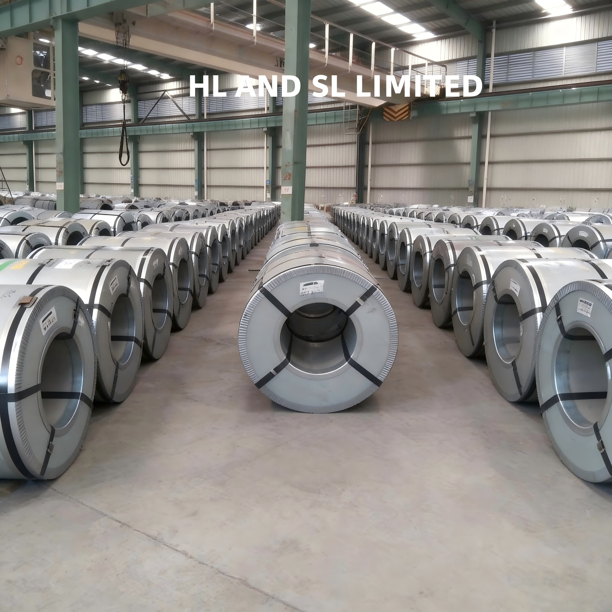
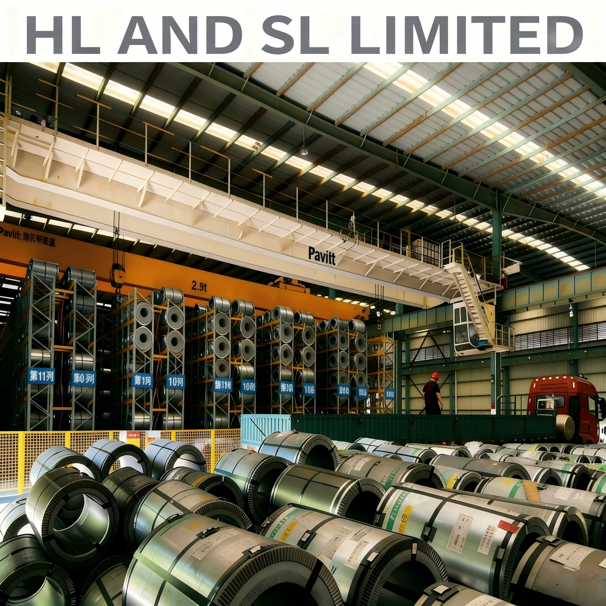
Define the grade, thickness, width, coil weight, coating, quantity and acceptance standard first, because those variables drive what can be quoted. HL AND SL LIMITED works in electrical steel export, was founded in 2012, operates a 30,000 m² processing facility with annual output of 30,000 t and an export share of 80%, serves markets including Mexico, Brazil, Italy, the UAE and India, and provides secondary processing to customer requirements for size, shape and performance. A specific 27Q095 or 27Q100 configuration can be quoted against those parameters, and the company brochure is available for download below.
Conclusion
The 27Q095 versus 27Q100 decision is a loss-budget decision wrapped around a circuit-type decision. Both are 0.27 mm Hi-B grain-oriented grades sharing the same thickness, Goss texture and B8 ≥1.88 T family specification. The separation is one loss tier: ≤0.95 W/kg against ≤1.00 W/kg at 1.7 T and 50 Hz, roughly a 5% step.
Run the numbers before choosing. Convert your no-load loss allowance into a W/kg ceiling using the effective core mass. If the allowance lands between 0.95 and 1.00 W/kg, or the application is a PV DC converter transformer or a high-efficiency power transformer operating close to the test flux, 27Q095 is the grade that covers the requirement. If the allowance clears 1.00 W/kg with margin and the circuit is a reactor or a general equipment core, 27Q100 is matched to the task without reserving margin the design will not use.
Then protect the decision downstream: screen the harmonic spectrum, match the coating to the operating temperature, control shearing and annealing, hold storage humidity at or below 60%, and put the standard, test condition and report requirements into the acceptance clause. The grade sets the ceiling; the process decides what you actually measure.
Specifying 27Q095 or 27Q100 for a core project?
Send the grade, thickness, width, coil weight, coating, quantity and acceptance standard, and the configuration can be quoted against those parameters. The full product and capability overview is available in the HL AND SL LIMITED brochure.
Have Questions or Need More Details?
Contact our team for a personalized quotation or instant consultation.
Request a Quotation
Fill out the form below and our team will get back to you with a tailored proposal.
WhatsApp Direct Chat
Prefer to chat in real-time? Message us on WhatsApp for instant assistance & quick answers.
- Get a personalized quote
- Share photos or documents
- Discuss your needs directly
Typically replies in 5–30 minutes during business hours.