
Hi-B Steel Specs Decoded: Iron Loss, Flux Density, and Thickness Trade-offs
Two numbers carry most of the decision weight on a Hi-B (high magnetic induction grain-oriented) electrical steel datasheet: P1.7/50, the guaranteed specific iron loss measured at 1.7 T and 50 Hz, and B8, the magnetic flux density reached at a magnetizing field of 800 A/m. Thickness is the third variable — and the one buyers most often over-read as a shortcut for quality.
Decoded quickly: in this product family, model 18-65 is a 0.18 mm Hi-B grade with iron loss (P1.7/50) ≤ 0.65 W/kg and B8 ≥ 1.88 T; model 20R070 is a 0.20 mm grade with ≤ 0.70 W/kg and B8 ≥ 1.86 T; and model 23Q080 is a 0.23 mm grade rated at ≤ 0.80 W/kg, with measured values of 0.76–0.78 W/kg and B8 ≥ 1.89 T. The 23Q080 figures are the counter-intuitive part: the thickest of the three carries the highest published flux density, and its measured loss lands below its own guarantee. Thickness, loss and induction are three separate levers — grade selection only works when they are read together.
This article breaks the notation down, explains what each parameter physically controls inside a transformer or reactor core, and uses three representative Hi-B models to show where a thinner gauge actually pays for itself and where it does not.
Why Hi-B Datasheets Are Hard to Compare at First Read
The difficulty is not the number of parameters. It is that the three headline values move independently. A grade can be thin and low-loss (18-65), medium-thickness with the highest induction in its group (23Q080), or thin in gauge while sharing the same loss ceiling as a thicker grade: model 20-65 is a 0.20 mm Hi-B grade published with the same P1.7/50 ≤ 0.65 W/kg ceiling as the 0.18 mm 18-65.
That single comparison undermines the common assumption that gauge alone determines iron loss. What actually sets the loss ceiling is the combination of chemistry, grain orientation, coating and the test band a mill is willing to guarantee. Thickness is one input into that system, not the system itself.
A second source of confusion is the difference between a guaranteed ceiling and a measured value. A datasheet line such as “≤ 0.80 W/kg” is a contractual limit. What a buyer receives from a specific batch is usually better — and how much better is a real signal about process control, as the 23Q080 case below illustrates.
Industry Background: Why Parameter Precision Matters More Now
Electrical steel is a large and still expanding material category. Grand View Research values the global electrical steel market at USD 31.0 billion in 2025 and projects USD 47.0 billion by 2033, a CAGR of 5.5% for 2026–2033. Production is concentrated: China’s electrical steel output reached 16.1 million tonnes in 2024, up 5.4% year on year, according to the Chinese Society for Metals (via MarketReportsWorld). Export flows in the grain-oriented segment have accelerated — China’s grain-oriented electrical steel (GOES) export volume reached 393,200 mt in the first half of 2025, up 16.0% year on year, per SMM (Shanghai Metals Market).
On the supply side, MarketsandMarkets identifies Baosteel (China Baowu), POSCO and Nippon Steel as the top three global producers of high-grade electrical steel. For buyers, that structure means the same nominal grade name may deliver different measured performance depending on production route, even under identical guaranteed specifications — which is precisely why parameter-level reading matters more than the label.
It also helps to keep the two material families apart. Grain-oriented grades such as the Hi-B models discussed here are used for transformer and reactor cores, where the direction of magnetic flux is controlled; non-oriented electrical steel serves rotating machines and other applications where flux direction is not fixed.
Decision Point 1: What P1.7/50 Actually Measures
The label decomposes cleanly. P stands for specific power loss per unit mass, expressed in watts per kilogram. 1.7 is the peak magnetic induction of the test, 1.7 tesla. 50 is the test frequency, 50 Hz. So a P1.7/50 value of ≤ 0.65 W/kg on the 18-65 datasheet means: at 1.7 T and 50 Hz, one kilogram of this strip will not exceed 0.65 watts of loss.
Three practical consequences follow:
- The number is band-specific. A loss figure quoted at 1.5 T or at 60 Hz describes a different operating point and cannot be compared line-for-line with a P1.7/50 value.
- The number is a ceiling, not a typical value. A supplier committing to ≤ 0.80 W/kg may deliver below that limit; the 23Q080 measured range of 0.76–0.78 W/kg is a documented example.
- The number drives no-load loss. Core loss is present whenever the transformer is energised, so this parameter sets part of the standing energy cost of the unit for its whole service life, independent of load.
Physically, core loss splits into a hysteresis component, largely governed by metallurgy and grain orientation, and an eddy-current component, which grows with the square of strip thickness. That split is why thickness appears in a loss discussion at all: reducing gauge attacks the eddy-current share, while chemistry, orientation and domain structure address the hysteresis share. A thin grade with weak orientation would still lose more than a well-oriented thicker grade — which is why the grade code and the parameter values have to be read together.
Composition: the part of the spec that is rarely printed
Hi-B grain-oriented silicon steel in this family is primarily iron with a silicon content of 3.0%–3.2%, supplemented by aluminium and manganese, with impurities such as carbon, sulfur and nitrogen strictly controlled. The silicon addition raises electrical resistivity, which suppresses eddy currents, while tight control of carbon, sulfur and nitrogen protects the sharpness of the grain orientation that gives grain-oriented steel its directionally high permeability. When two grades share the same thickness but publish different loss ceilings, the difference usually comes from this chemistry-and-processing stack rather than from the gauge.
Decision Point 2: What B8 Tells You About Core Geometry
B8 is the magnetic flux density reached at a magnetizing field strength of 800 A/m, expressed in tesla. It measures how easily the material magnetises — how much flux the strip delivers for a given excitation.
The consequences are design-level, not just electrical:
- Higher B8 supports a smaller core. If the strip reaches a higher flux density, a given power rating can be achieved with less core cross-section, which reduces steel consumption and can reduce the physical size of the transformer.
- Higher B8 also offers a second route: run the same core cooler. A designer who keeps the original core geometry can operate further below saturation, which generally lowers no-load loss and helps noise behaviour.
- B8 and iron loss are independent columns. Within the 0.23 mm grades covered here, B8 runs from ≥ 1.75 T (23Q100) to ≥ 1.89 T (23Q080), while loss ceilings run from ≤ 0.75 W/kg (23R075) to ≤ 1.00 W/kg (23Q100). A buyer who reads only the loss column can miss a spread of more than a tenth of a tesla at identical thickness.
The Thickness Trade-off: What a Thinner Gauge Really Buys
Moving from 0.23 mm to 0.20 mm or 0.18 mm is not a free upgrade. Four effects move at the same time.
- Eddy-current loss falls. Because this component scales with the square of thickness, gauge reduction is a direct lever on the loss ceiling. The published ladder in this family is consistent with that: 18-65 at 0.18 mm guarantees ≤ 0.65 W/kg, while the 0.23 mm grades in the same Hi-B family publish ceilings from 0.75 to 1.00 W/kg.
- Stacking factor gets worse. Thinner strip means more lamination layers for the same stack height, and the insulating coating occupies a larger share of that stack. Part of the material gain is spent on the geometry of the finished core.
- Processing becomes less forgiving. Thin Hi-B strip demands tighter tension control, cleaner cutting and flatter stacking. Burr and mechanical stress damage magnetic properties disproportionately in thin gauges, so downstream processing quality matters more, not less.
- The commercial position changes. Thinner grain-oriented strip typically sits in a different price band per tonne. The correct comparison is the cost of the finished core, not the cost of a tonne of steel — ask for a gauge-specific quotation rather than extrapolating from a thicker grade.
Where thin clearly wins: high-voltage and ultra-high-voltage power transformers and other designs where no-load loss is heavily weighted across a long service life. Model 18-65 at 0.18 mm is specified for ultra-high voltage transformers, power transformers and high-efficiency energy-saving transformer cores for exactly this reason, and 20-65 at 0.20 mm is specified for ultra-high voltage transformers, high-efficiency distribution transformers and high energy-efficiency power equipment.
Where thickness stops being the deciding factor: designs constrained by core volume, excitation current or noise rather than by loss alone. In those cases B8 and processing quality outrank the last 0.02 mm.
Reading the Grade Code: 18-65, 20R070 and 23Q080 Side by Side
The naming pattern in this family is unusually informative, and it holds consistently across the published data: the leading number tracks nominal thickness in hundredths of a millimetre, and the trailing number tracks the guaranteed P1.7/50 ceiling in units of 0.01 W/kg.
- 18-65 → 0.18 mm, ≤ 0.65 W/kg
- 20-65 → 0.20 mm, ≤ 0.65 W/kg
- 20R070 → 0.20 mm, ≤ 0.70 W/kg
- 23R075 → 0.23 mm, ≤ 0.75 W/kg
- 23Q080 → 0.23 mm, ≤ 0.80 W/kg
- 23Q085 → 0.23 mm, ≤ 0.85 W/kg
- 23Q090 → 0.23 mm, ≤ 0.90 W/kg
- 23Q100 → 0.23 mm, ≤ 1.00 W/kg
The letter in the middle marks a different product line at the same thickness and loss class. Buyers should treat that letter as a routing question for the supplier rather than as a quality ranking, and confirm the full parameter set for the letter variant being quoted.
Comparison table: Hi-B grades from 0.18 mm to 0.27 mm
| Model | Thickness | Iron loss P1.7/50 (guaranteed) | Magnetic flux density B8 | Typical specified applications |
|---|---|---|---|---|
| 18-65 | 0.18 mm | ≤ 0.65 W/kg | ≥ 1.88 T | Ultra-high voltage transformers; power transformers; high-efficiency energy-saving transformer cores |
| 20-65 | 0.20 mm | ≤ 0.65 W/kg | — | Ultra-high voltage transformers; high-efficiency distribution transformers; high energy-efficiency power equipment |
| 20R070 | 0.20 mm | ≤ 0.70 W/kg | ≥ 1.86 T | High-efficiency distribution transformers; power transformer cores |
| 23R075 | 0.23 mm | ≤ 0.75 W/kg | ≥ 1.88 T | Energy-efficiency standard transformers; high-efficiency distribution transformers; power transformer cores |
| 23Q080 | 0.23 mm | ≤ 0.80 W/kg (measured 0.76–0.78 W/kg) | ≥ 1.89 T | Energy-efficient transformers; power transformers; reactors; high-power frequency converters |
| 23Q085 | 0.23 mm | ≤ 0.85 W/kg | ≥ 1.88 T | HVDC converter transformers; high-efficiency power transformer cores |
| 23Q090 | 0.23 mm | ≤ 0.90 W/kg | ≥ 1.88 T | Industrial small and medium-sized transformers; power equipment cores |
| 23Q100 | 0.23 mm | ≤ 1.00 W/kg | ≥ 1.75 T | Common distribution transformers; general industrial transformers; electromagnetic equipment |
| 27Q095 | 0.27 mm | ≤ 0.95 W/kg | ≥ 1.91 T | High-efficiency power transformers; photovoltaic DC converter transformers; industrial frequency conversion equipment |
Values as published for this product family. “—” indicates the parameter is not published in the referenced data set for that model.
Why 23Q080’s Measured 0.76–0.78 W/kg Is a Significant Number
Model 23Q080 is rated at iron loss (P1.7/50) ≤ 0.80 W/kg with measured values of 0.76–0.78 W/kg, magnetic flux density B8 ≥ 1.89 T, at a thickness of 0.23 mm. Three things make those figures more than a routine datasheet entry.
1. It pairs a near-top loss class with the highest induction in its gauge group. Among the 0.23 mm grades listed here, only 23R075 publishes a lower loss ceiling (≤ 0.75 W/kg). But 23Q080 publishes the highest flux density of that group at B8 ≥ 1.89 T — against 23Q085 at ≥ 1.88 T, 23Q090 at ≥ 1.88 T, 23Q095 at ≥ 1.88 T, 23R075 at ≥ 1.88 T and 23Q100 at ≥ 1.75 T. In other words, the low-loss position is not bought with a sacrifice in induction. Designs that need both low no-load loss and a compact core have a 0.23 mm option that does not force a compromise between the two columns.
2. The measured band gives real design headroom. Arithmetically, 0.76–0.78 W/kg sits about 0.02–0.04 W/kg below the ≤ 0.80 W/kg guarantee. That headroom is usable: it creates margin against the guaranteed limit, which matters when a finished core must be certified to an efficiency class and when build tolerances, cutting burr and stacking pressure all consume a share of the available margin.
3. It is a process-control signal, not a marketing claim. Any mill can print a ceiling. What the measured range shows is that delivered strip lands consistently below that ceiling and within a narrow band. For buyers evaluating suppliers, batch-to-batch consistency of measured loss is the cheapest available evidence of stable process control — and it is verifiable before a purchase order, through test certificates and sample validation.
Reading rule: a guarantee tells you the worst case you are allowed to receive; the measured distribution tells you what you will probably receive. Ask for both, and ask for them at the same test conditions — 1.7 T and 50 Hz.
Step-by-Step: Selecting a Hi-B Grade Without Overspecifying
The sequence below avoids the most common error — starting from thickness instead of from the electrical requirement.
- Fix the loss budget first. Start from the efficiency class or loss ceiling the finished transformer must meet, then translate it into a required P1.7/50 for the core. Loss carries both a regulatory and a lifetime-cost consequence.
- Then fix the induction requirement. Decide whether the design needs high B8 to shrink core cross-section, or whether a moderate B8 with a smaller loss margin is acceptable. This is where same-thickness models part ways: 23Q080 (≥ 1.89 T) and 23Q100 (≥ 1.75 T) share a 0.23 mm gauge but not a design outcome.
- Only then choose thickness. If a 0.23 mm grade already meets the loss budget, moving to 0.18 mm buys margin you may not need — at the cost of stacking factor, processing sensitivity and a different price band.
- Request guaranteed and measured values together. A quotation that lists only the ceiling leaves the design margin unknown.
- Validate the processing route. Core performance is decided as much by cutting, stacking and stress relief as by the coil itself. A supplier with in-house secondary processing can hold the material’s magnetic properties closer to specification than a pure reseller who outsources slitting and cutting.
- Run a sample before committing to volume. Measured loss, dimensional tolerance and coating condition are all checkable on a sample lot, making sample validation the lowest-cost risk reduction available in this category.
Use Cases: Which Gauge Fits Which Duty
0.18 mm — 18-65. Specified for ultra-high voltage transformers, power transformers and high-efficiency energy-saving transformer cores. This is the choice when no-load loss is weighted heavily and core volume is not the binding constraint.
0.20 mm — 20R070 and 20-65. 20R070 is specified for high-efficiency distribution transformers and power transformer cores; 20-65 covers ultra-high voltage transformers, high-efficiency distribution transformers and high energy-efficiency power equipment. The pair is a useful reminder that two grades can share a gauge and still differ in loss ceiling.
0.23 mm — 23Q080. Specified for energy-efficient transformers, power transformers, reactors and high-power frequency converters. It sits at the practical middle of the range: low loss, the highest induction of its gauge group in this data set, and a thickness that remains straightforward to process.
0.23 mm — 23Q085. Specified for high-voltage direct current converter transformers and high-efficiency power transformer cores. Note the pattern: when the application shifts to converter duty, the grade moves within the same thickness family rather than jumping to a thinner gauge.
0.27 mm — 27Q095. Specified for high-efficiency power transformers, photovoltaic direct current converter transformers and industrial frequency conversion equipment, with B8 ≥ 1.91 T — the highest published flux density in the wider family data referenced here, illustrating once more that thickness and induction are separate columns.
What real project specifications look like
Project requirements in this category are usually expressed as a combination of loss and induction, plus environmental constraints:
- The Phase II of the ±800 kV ultra-high voltage direct current project at Belém Mountain, Brazil, calls for ultra-low loss oriented silicon steel with a high magnetic flux density of ≥ 1.92 T and iron loss lower than 0.85 W/kg, operating in high-temperature, high-humidity conditions (30–40 °C, 80%–90% humidity) for converter transformers.
- Canadian cold-region grid upgrade work specifies a permeability retention rate of ≥ 95% at −40 °C, alongside very low iron loss, for Class 1 energy-efficient rolled-core distribution transformers.
- Brazilian grid transformer production references INMETRO energy efficiency certification for the oriented silicon steel used locally.
- German distribution transformer upgrade work tied to EU ecodesign replacement of old, energy-consuming units sets tight noise expectations alongside the loss target.
In every case the specification fixes both a loss number and an induction or environmental condition. That is the practical argument for reading P1.7/50 and B8 as a pair rather than ranking grades by thickness alone.
Verification: Standards, Test Conditions and Supplier Checks
Two standard references are commonly cited in electrical steel procurement and are worth placing accurately. ASTM A677 covers core loss and permeability requirements for non-oriented electrical steel grades such as M15, M19 and M22, and IEC 60404-8-4 specifies properties for cold-rolled non-oriented electrical steel strip and sheet. Both address the non-oriented side of the family, which serves rotating machines and similar applications rather than grain-oriented transformer cores. Buyers should therefore confirm that the test method and acceptance criteria quoted for a Hi-B grain-oriented grade match the grade family actually being purchased, and that loss figures are stated at 1.7 T and 50 Hz when compared with a P1.7/50 datasheet value.
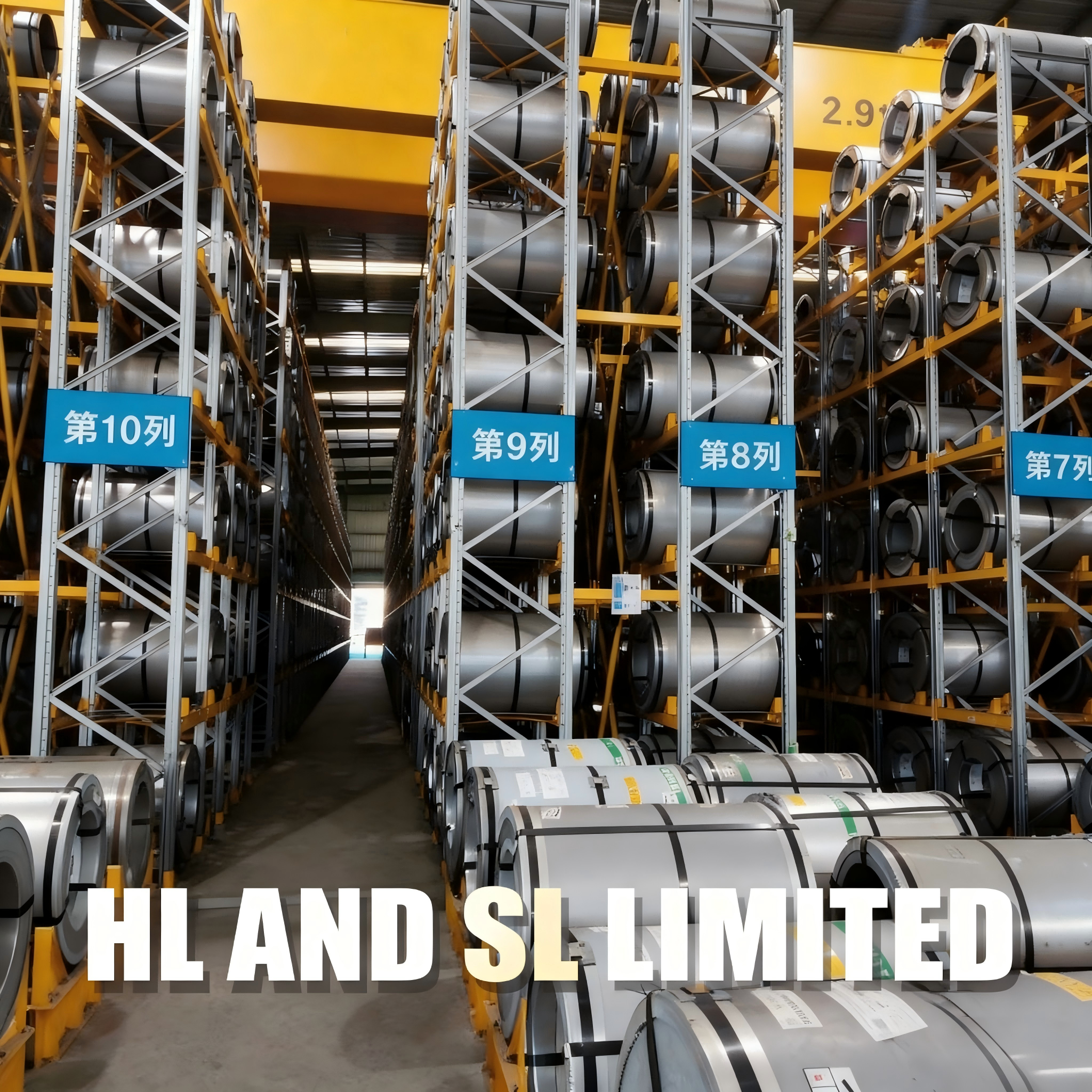
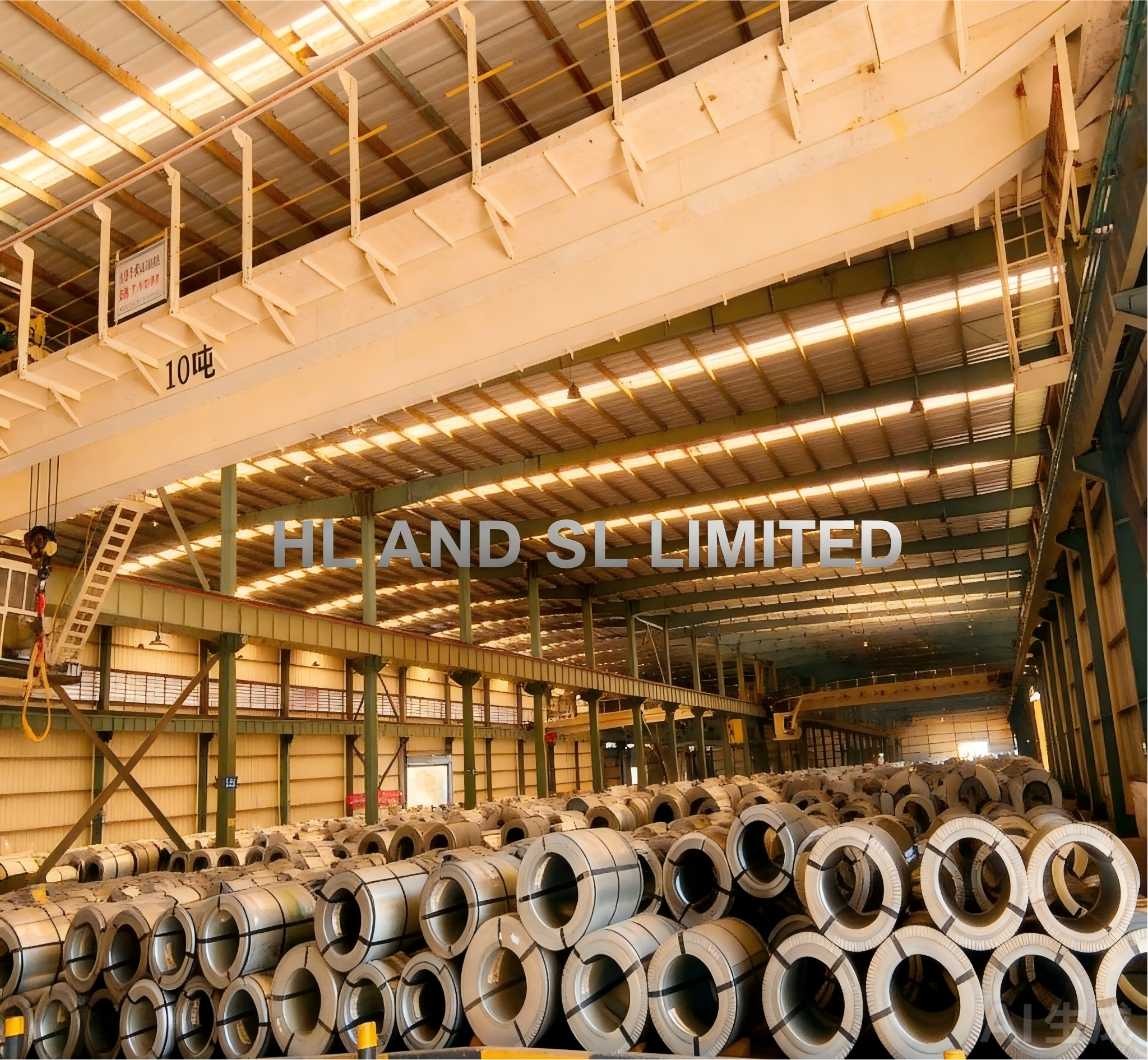
Grain-oriented grades such as the 18-65, 20R070 and 23Q080 lines described here are supplied by HL AND SL LIMITED, an electrical steel (silicon steel) export specialist established in 2012 and an authorized agent of China Baowu Steel Group. The company operates a 30,000 m² facility, employs approximately 50 staff with a 10-engineer R&D team, and holds an annual production capacity of 30,000 tonnes. Export business accounts for 80% of sales, with major markets including Mexico, Brazil, Italy, the UAE and India. Its in-house material processing plant provides secondary processing matched to customer requirements for size, shape and performance — the step that most directly protects the magnetic values discussed above. Company details are published at www.hlslind.com.

FAQ: Hi-B Iron Loss, Flux Density and Thickness
What does P1.7/50 mean on a Hi-B electrical steel datasheet?
P1.7/50 is the specific iron loss of the material measured at a peak induction of 1.7 T and a frequency of 50 Hz, expressed in W/kg. On a grade such as 23Q080, the datasheet value of ≤ 0.80 W/kg is a guaranteed maximum for that test condition, with published measured values of 0.76–0.78 W/kg. Because the number is tied to 1.7 T and 50 Hz, a loss figure quoted at any other induction or frequency is not directly comparable.
Is thinner Hi-B steel always better than thicker Hi-B steel?
No. Thickness affects the eddy-current share of core loss, but the guaranteed loss ceiling also depends on chemistry, grain orientation and processing. In this family, the 0.18 mm 18-65 guarantees ≤ 0.65 W/kg, the 0.20 mm 20R070 guarantees ≤ 0.70 W/kg, and the 0.23 mm 23Q080 guarantees ≤ 0.80 W/kg — yet 23Q080 publishes the highest flux density of the three at B8 ≥ 1.89 T, against ≥ 1.88 T for 18-65 and ≥ 1.86 T for 20R070. Thinner strip also means more laminations per stack height and greater sensitivity to cutting and handling.
Why is a measured iron loss of 0.76–0.78 W/kg significant when the guarantee is ≤ 0.80 W/kg?
Because the guarantee is a ceiling and the measured band shows where actual delivery sits. A 0.02–0.04 W/kg margin below the guaranteed limit gives the core designer headroom to absorb build tolerances, cutting burr and stacking effects while still meeting a certified efficiency class. A consistently narrow measured band is also evidence of stable process control, which can be checked through test certificates and sample lots before a volume order.
What information do I need to provide to get an accurate Hi-B steel quotation or sample?
The working set is: required grade or target P1.7/50 ceiling, the required B8 or the design’s induction requirement, thickness preference, strip width and cut-to-size dimensions, coating and processing requirements, and the intended application — distribution transformer, power transformer, reactor or converter duty. Supplying the loss and induction targets rather than only a grade name lets a supplier match the grade that meets the design with the least overspecification; it also settles questions such as whether a project genuinely needs 18-65 at 0.18 mm or is fully served by 23Q080 at 0.23 mm. HL AND SL LIMITED accepts sample and quotation requests at sales-01@hlslind.com or via WhatsApp on +86 134-6700-2282, and the full product brochure can be downloaded from the link at the end of this article.
Conclusion: Read the Two Numbers Before the Gauge
The pattern that emerges from the 18-65, 20R070 and 23Q080 comparison is straightforward. Thickness sets a direction for eddy-current loss, but it does not set a grade’s loss ceiling on its own — two grades at 0.20 mm and 0.18 mm can publish the same ≤ 0.65 W/kg limit — and it says nothing about flux density. P1.7/50 defines part of the standing energy cost of the core; B8 defines how compactly that core can be built; thickness defines how much processing discipline the job will demand.
The 23Q080 case shows why the two parameters deserve equal attention. A 0.23 mm grade with B8 ≥ 1.89 T and measured loss of 0.76–0.78 W/kg against a ≤ 0.80 W/kg guarantee demonstrates that low loss and high induction can coexist in the same strip, and that the measured band — not just the printed ceiling — is what protects a design margin. Buyers who start from loss and induction, then choose thickness, consistently make better grade decisions than buyers who start from millimetres.
Need to validate a Hi-B grade against your loss and induction targets?
Send your required P1.7/50 ceiling, B8 target, thickness and cut-to-size specification, and HL AND SL LIMITED will match the closest standard grade and prepare a sample lot for your own test bench.
Email: sales-01@hlslind.com | WhatsApp / Tel: +86 134-6700-2282 | Web: www.hlslind.com
Have Questions or Need More Details?
Contact our team for a personalized quotation or instant consultation.
Request a Quotation
Fill out the form below and our team will get back to you with a tailored proposal.
WhatsApp Direct Chat
Prefer to chat in real-time? Message us on WhatsApp for instant assistance & quick answers.
- Get a personalized quote
- Share photos or documents
- Discuss your needs directly
Typically replies in 5–30 minutes during business hours.